Braking Performance I: How to Translate Reality into Simulation
Understanding how a braking system works is one of the key factors in achieving a competitive advantage in motorsport, where braking performance directly translates into lap time, and in the automotive industry, where brake design is critical for safety and durability.
Replicating both the exact physical forces and the feeling of a real braking system in a driving simulator has always been a challenge. A wide range of physical solutions have been developed to address this: real discs and pads connected to simulators, pedals using springs and dampers to mimic hydraulic behaviour, and many others.
However, what happens when we want to simulate a change in master cylinder size, or evaluate a different brake pad compound? Both the required pedal force and the pedal feel change, and accurately translating these effects into a simulator has traditionally been difficult — until now.
How a Braking System Works
Let us briefly review how a braking system operates in reality.
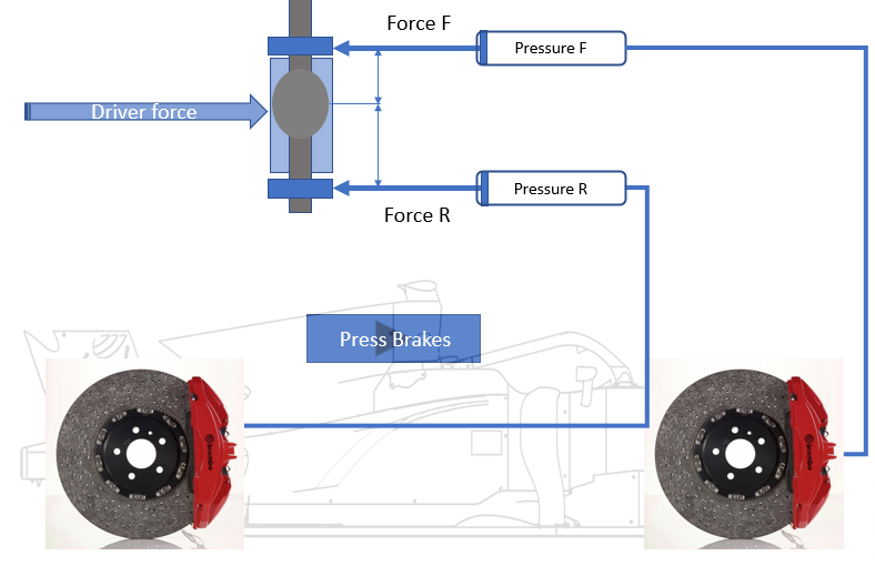
In motorsport, the driver applies a force to the brake pedal. This force is transmitted through a rod to a mechanical brake balance system. Depending on the position of the balance bar — which can be adjusted by the driver — the force is distributed between two master cylinders (front and rear).
These master cylinders convert the applied force into hydraulic pressure, which is then transmitted through the brake lines to the calipers, where the hidraulic pressure is converted again into force, through the pistons, then pads, discs, and finally to the tyres.
In road cars, the most common system uses a tandem master cylinder. Due to weight transfer during braking, more force is required at the front axle than at the rear. This is achieved primarily through design.
Unlike in motorsport, where front and rear brake systems are often similar, road cars typically use larger front discs and different piston sizes to generate higher braking forces at the front axle.
Additionally, a proportioning valve (or electronic brakeforce distribution system) is used to limit the pressure sent to the rear axle beyond a certain threshold, effectively creating a dynamic brake bias.
Bringing Reality into Simulation
To accurately replicate braking in a simulator, we must separate the problem into three key aspects:
- Brake pressure vs longitudinal acceleration.
- Brake pressure calculation from pedal force.
- Matching brake pedal feel.
Only when the three of them are correctly modelled can a braking event feel truly realistic.
Brake pressure vs longitudinal acceleration
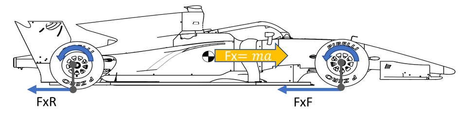
Before even starting working in a driving simulator, we must ensure that our vehicle and tyre model translate properly the brake pressure into longitudinal acceleration.
To do so, the calipers and pistons must be correctly modelled so that the pressure coming from the brake lines is transformed like in reality into the force acting through the pads and discs which together with the friction coefficient will generate the correct braking torque on the wheel. Finally, with a proper tyre model, this force is transformed into longitudinal acceleration.
We will asume for the moment that you already did this part of the job, let's see how our driving simulator can transform pedal force into the correct brake pressures that will feed our vehicle and tyre models.
Brake pressure calculation from pedal force
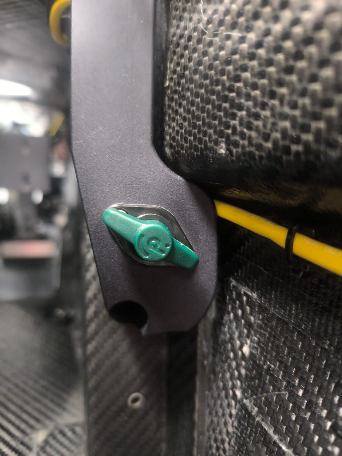
We begin by defining in the vehicle section of the Control Panel in the Etecmo Simulation Suite, master cylinder size, distance from shaft to master cylinder rod, and hidraulic brake bias are inputs as seen in the image below
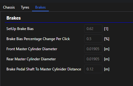
And as there is a driving simulation running, both the force at the pedal and hidraulic BB changes are inputs as well, this last one being changed by a rotational switch.
To compare real-life driving with simulator behaviour, we must define a common variable. The most suitable choice is the torque at the base of the pedal.
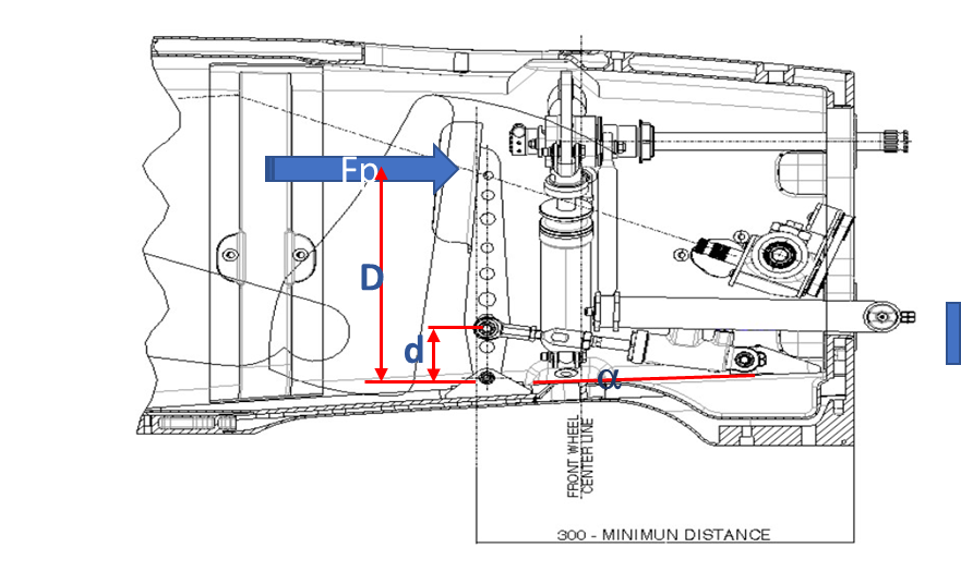
Why torque? Because pedal geometry differs between real and simulated systems. Comparing forces directly would therefore be misleading. By converting both to torque, we obtain a consistent reference:

Where:
- F = pedal force
- D = pedal lever arm
Hydraulic Pressure Calculation
The force transmitted to the master cylinders is:
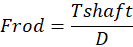
Where:
- T_pedal = pedal torque
- D = pedal base-rod distance
The pressure in each circuit is then:
P = F / A
Mechanical vs Hydraulic Brake Bias
A key challenge arises when the master cylinders have different diameters.
A 50% mechanical brake bias does not result in a 50% hydraulic brake bias unless both master cylinders have the same area.
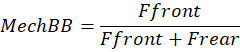
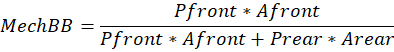
Hydraulic brake bias is defined as:

Mechanical brake bias is:
Since:
F = P · A
Then:
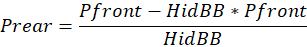
Using the HidBB equation:
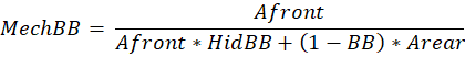
After substitution and simplification into the MechBB equation, the relationship becomes:
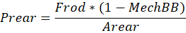
Final Pressure Calculation
Once the correct mechanical brake bias is known, the pressures can be calculated:

This ensures that:
- The hydraulic brake bias matches the target value
- The pedal force required matches real life
If the brake system and tyre model are correctly implemented, the resulting longitudinal acceleration will match real-world behaviour.
Automotive Case
In road car systems, there is no adjustable mechanical brake bias. Therefore:
- No mechanical bias calculation is required
- Pressure distribution is governed by system design and proportioning valves
Matching the brake pedal feeling
Once force matching is achieved, the next step is replicating pedal feeling.
Even if the forces match perfectly, the driver may still perceive differences. This is due to two remaining variables:
- Pedal stiffness
- Free play
To evaluate these, we compare real and simulated data using an XY plot of pedal force vs pedal displacement.
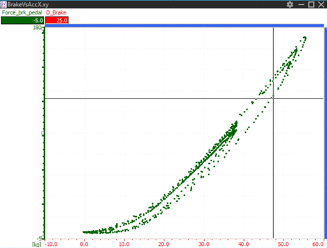
A typical curve shows:
- An initial free play region (displacement with negligible force)
- A nonlinear (concave) region where stiffness increases
The steeper the curve, the stiffer the pedal.
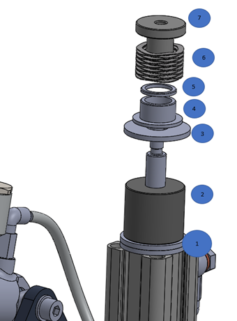
To match this behaviour in our simulator, hardware elements such as:
- Springs
- Elastomers
- Spacers
are adjusted until the curves align.
Once both curves match, the simulator reproduces both the stiffness and the free play of the real car.
Motorsport Case Study: Master Cylinder Change
Changing master cylinders during a race weekend is often a complex and time-consuming process. It requires:
- System bleeding
- Hardware changes
- Driver adaptation to new pedal feel
This can lead to difficult trade-offs. For example, a master cylinder combination may reduce undesirable brake bias migration, but the driver may not be comfortable with the resulting pedal feel.
Using the methodology described above, these changes can be evaluated offline.
- The effect on braking force can be simulated instantly by modifying master cylinder diameters
- Pedal feel can be replicated using pre-recorded force vs displacement curves
A practical approach is:
- Test different master cylinder combinations in the workshop
- Record pedal force vs displacement curves
- Replicate each curve in the simulator using mechanical adjustments
This allows full evaluation of braking system changes before arriving at the track.
Conclusion
By separating braking performance into:
- Brake pressure into longitudinal acceleration matching
- Pedal force into brake pressure matching
- Feel matching
it is possible to achieve a high level of realism in simulation, even more in a laser scanner environment where every bump is where is supposed to be.
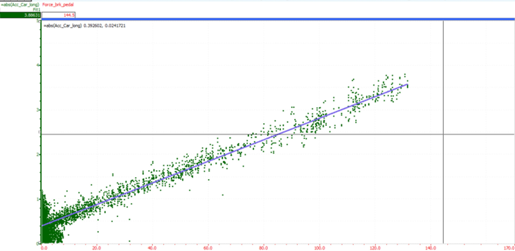
Once all three aspects have been achieved, the graph pedal force vs longitudinal acceleration should match perfectly simulation vs reality data, and it should look like the one below.
This enables engineers and drivers to:
- Accurately predict system changes
- Reduce track testing time
- Improve performance more efficiently
Did you enjoy this article?
In the next part, we will explore advanced braking performance analysis techniques and how to extract maximum performance from your braking system.